In video 5 we saw how we can connect multiple LEDs to the Arduino via a relay or a FET switch module. With those we can switch the higher currents needed for say street lights on a model layout. In video 4 we simulated a night cycle, triggered by a push button. Why not make this a fully automatic day & night cycle, with an on/off toggle switch?
These are the specifications for our new software:
- Create a fully automatic day & night cycle, with 2 easy configurable times.
- A toggle switch on our switch panel will be used to turn the cycle on or off.
- A LED on our switch panel should show when the cycle is running.
Read on below the video …
For the new software we can re-use the code we wrote in video 4. We already have the push button input there, we simply change the name. We also have a delay() for the night time. If we add a ‘day time’ delay and modify the #defines we should be almost there.
#define DAY_NIGHT_CYCLE_ON_OFF_PIN 2 // input for toggle switch
#define LIGHTS_PIN 8          // output to FET or relay module
#define DAY_TIME 180000              // [ms]
#define NIGHT_TIME 180000            // [ms]

void setup() {
  pinMode(DAY_NIGHT_CYCLE_ON_OFF_PIN, INPUT_PULLUP);
  pinMode(LIGHTS_PIN, OUTPUT);
}

void loop() {
  if (digitalRead(DAY_NIGHT_CYCLE_ON_OFF_PIN) == LOW) {
    digitalWrite(LIGHTS_PIN, HIGH);
    delay(NIGHT_TIME);
    digitalWrite(LIGHTS_PIN, LOW);
    delay(DAY_TIME);
  }
}
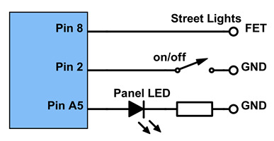 We’re not done, our specifications said to add an indicator LED on the switch panel. On an Arduino pins A0-A5 are labeled as ‘ANALOG IN’ … can we use those as digital output? Let’s just try and connect pin A5. The image shows the wiring diagram we now have. Let’s add the #define for the switch panel LED. In ‘setup’ we add a pinMode, in the ‘if’ we add the digitalWrite and we also add an ‘else’, to turn the LED off again. The added lines are shown in red.
#define DAY_NIGHT_CYCLE_ON_OFF_PIN 2 // input for toggle switch
#define LIGHTS_PIN 8                 // output to FET or relay module
#define LED_PIN A5                   // output to LED on switch panel
#define DAY_TIME 180000              // [ms]
#define NIGHT_TIME 180000            // [ms]

void setup() {
  pinMode(DAY_NIGHT_CYCLE_ON_OFF_PIN, INPUT_PULLUP);
  pinMode(LIGHTS_PIN, OUTPUT);
  pinMode(LED_PIN, OUTPUT);
}

void loop() {
  if (digitalRead(DAY_NIGHT_CYCLE_ON_OFF_PIN) == LOW) {
    digitalWrite(LED_PIN, HIGH);
    digitalWrite(LIGHTS_PIN, HIGH);
    delay(NIGHT_TIME);
    digitalWrite(LIGHTS_PIN, LOW);
    delay(DAY_TIME );
  }
  else {
    digitalWrite(LED_PIN, LOW);
  }
}
Note: with the analog pins we can use their names A0 – A5 as well as the numbers 14 – 19: digitalRead(A5) renders the same result as digitalRead(19).
We’re almost there. It’s just that I don’t like those very large numbers for the timers in the #defines. The delay() command uses milliseconds, but I’d rather use minutes, or seconds at most, if we like to have finer control. OK … let’s use seconds in the #defines and let’s multiply those by 1000 inside the delay() command. Yes, the Arduino is a computer … it knows how to multiply. Changed lines are shown in red.
// USER CONFIGURATION
#define NIGHT_TIME 180 // [s] 180 = 3 minutes
#define DAY_TIME 180   // [s]
// END USER CONFIGURATION

#define DAY_NIGHT_CYCLE_ON_OFF_PIN 2 // input for toggle switch
#define LIGHTS_PIN 8                 // output to FET or relay module
#define LED_PIN A5                   // output to LED on switch panel

void setup() {
  pinMode(DAY_NIGHT_CYCLE_ON_OFF_PIN, INPUT_PULLUP);
  pinMode(LIGHTS_PIN, OUTPUT);
  pinMode(LED_PIN, OUTPUT);
}

void loop() {
  if (digitalRead(DAY_NIGHT_CYCLE_ON_OFF_PIN) == LOW) {
    digitalWrite(LED_PIN, HIGH);
    digitalWrite(LIGHTS_PIN, HIGH);
    delay(NIGHT_TIME * 1000);
    digitalWrite(LIGHTS_PIN, LOW);
    delay(DAY_TIME * 1000);
  }
  else {
    digitalWrite(LED_PIN, LOW);
  }
}
Note that the symbol used for multiplication is * , not x .
Time to test. For test purposes we best set the day and night times short, say 2 and 3 seconds.
Yes that works! Hey … wait a sec … does this not look like the ‘Blink’ sketch that we used to test the connection all the way back in video 1? Yes it does. We just wrote our own Blink, with a few twists. We can turn the cycle on and off with a switch and an indicator LED shows the status. And … our code is easy to read and is easy to modify.
Are you still here? On to the next challenge then. On our model railway layout we don’t have just one light group, we have multiple. We have street lights, we have house lights and we also have station lights. We want all of these to run on the day & night cycle, but … they should not switch on and off all at the same time, that would look unrealistic.
— 0 —

Hello Rudy, Just ordering a few bits so i can join in as we go! I need a 12 volt power supply but there are so many different types? I know i need a 240 volt to 12 volt DC power supply but there are different amperage ones out there, you can get a 1 amp a 2 amp or a 5 amp? can you advise which one would be best, as i want to use it for my layout eventually.
Thanks a lot Phil Newman (P.S. i am the chap who watches your videos on Youtube normally)
LikeLike
Hi Phil. It depends entirely on the application how heavy a power supply you need. I’ll send you an email then we can discuss.
LikeLike