To operate the railway crossing we need to detect if a train is nearing and also when it has passed by. Several detection methods are in use among model railway hobbyists:
- Rail current detection
- A reed switch on the track and a magnet under the rolling stock
- An optical sensor, via reflection or via beam interrupt
- Other, more exotic methods
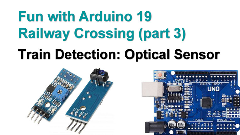
 Any method will work, as long as the detector sends a logical LOW (0V) or HIGH (5V) to the Arduino. In this video, two TCRT5000 optical sensors are used, for the only reason that I had them lying around and that they can easily be placed alongside the track.
These sensors are cheap, but they are somewhat susceptible to bright environment light. There are other sensors that use a 38kHz signal with the transmitter and that have a 38kHz filter on the receiver side, these are less susceptible to environmental light.
The sensors are of the reflection type. The blue component is an infra red transmitter, the black one is an IR receiver that detects reflected light. The potentiometer can be used to tune the sensitivity. Find the point where the sensor is always on even when not reflecting on anything. Then with your application, while it is reflecting, find the point where the sensor goes off. The middle between these two is a good point for the sensitivity.
The sensors are impossible to hide along the track. There are two solutions to that. The sensors can be mounted under the track, looking upwards through a hole to reflect against the underside of the train. An even better way is to cut off the transmitter and receiver and connect them to the PCB with 4 wires. They can then be placed alongside the track, just above the rail, opposite to each other. They are small enough to be easily hidden. The detector now is of the beam interrupt type, it is always ‘on’, until a train interrupts the IR beam. This is more reliable than reflection, and also this setup is less susceptible to environment light.
To connect to the Arduino, use the digital output. Some types also have an analog output, but I would not bother using that.
Read on below the video …
Let’s see if both sensors detect a train with this little test code:
#define SENSOR1_PIN 10
#define SENSOR2_PIN 11

void setup() {
  pinMode(SENSOR1_PIN, INPUT_PULLUP);
  pinMode(SENSOR2_PIN, INPUT_PULLUP);
  Serial.begin(9600);
  Serial.println("Sensor Test");
}

void loop() {
  if(digitalRead(SENSOR1_PIN) == LOW)
    Serial.println("Sensor 1 detected");
  if(digitalRead(SENSOR2_PIN) == LOW) {
    Serial.println("Sensor 2 detected");
}
 Well … yes, that works OK. Let’s have some fun now and build ourselves a speed measurement system. This is the State Transition Diagram. We’ve seen in video 17 how we can translate this into code, in 5 simple steps. Step 1 and 2 first: every state and every transition become a case inside a switch():
switch (state) {
  case 1: // idle, wait for sensor 1
    if(digitalRead(SENSOR1_PIN) == LOW) transition = 12;
  break;
  case 2: // measurement started, wait for sensor 2
    if(digitalRead(SENSOR2_PIN) == LOW) transition = 21;
  break;
}

switch (transition) {
  case 12:
    // start measurement
    transition = 0;
    state = 2;
  break;
  case 21:
    // stop measurement, calculate and print speed
    transition = 0;
    state = 1;
  break;
}
Now we add our #defines, our variable declarations and setup(), and the code to start the time measurement in transition 12, and to stop and calculate the scale speed in transition 21. Of course we need to measure the distance between the sensors with a tape ruler and fill it in at #define DISTANCE.
#define SENSOR1_PIN 10
#define SENSOR2_PIN 11
#define DISTANCE 350 // [mm]

byte state = 1, transition;
unsigned long start_ms;
unsigned long measured_ms;
float mm_per_second;

void setup() {
  pinMode(SENSOR1_PIN, INPUT_PULLUP);
  pinMode(SENSOR2_PIN, INPUT_PULLUP);
  Serial.begin(9600);
  Serial.println("Speed Measurement System Ready");
  Serial.println("Waiting for sensor 1");
}

void loop() {

  switch (state) {
    case 1: // waiting for sensor 1
      if(digitalRead(SENSOR1_PIN) == LOW) transition = 12;
    break;
    case 2: // measurement started, waiting for sensor 2
      if(digitalRead(SENSOR2_PIN) == LOW) transition = 21;
    break;
  }

  switch (transition) {
    case 12:
      Serial.println("Sensor 1: start measurement");
      start_ms = millis();
      transition = 0;
      state = 2;
    break;
    case 21:
      measured_ms = millis() - start_ms;
      Serial.println("Sensor 2:  stop measurement");
      Serial.println();
      Serial.print(DISTANCE);
      Serial.print(" mm in ");
      Serial.print(measured_ms);
      Serial.println(" milliseconds");
      mm_per_second = (float)DISTANCE * 1000 / measured_ms;
      Serial.print(mm_per_second);
      Serial.println("   mm/s");
      Serial.print(mm_per_second * (float)3.6 * 87 / 1000);
      Serial.println("   km/hr (HO scale)");
      Serial.println();
      Serial.println("Waiting for sensor 1");
      transition = 0;
      state = 1;
    break;
  }
}
Note the new variable type that is used: float. We want to represent the calculated speed as a ‘floating point’ number, like 37.46 km/hr … the float variable takes care of this automatically.
Let’s test it. Yes … it works great. It could be fun to have this as a permanent setup somewhere along our track, with the speed shown on an LCD or an OLED maybe? Who knows we’ll do just that in a future video.
But first we have a railway crossing to finish. We have all the ingredients now: blinking LEDs, a servo that operates the gate, sensors that detect the train. In the next video we will combine this all together and create the code for our automatic model railway crossing, based on its State Transition Diagram.
— 0 —

Excellent series Rudy,
Thank you for presenting so well.
Have implemented your reed switch detection system and reversing loop which work very reliably, set and forget.
Really enjoy these videos as you explain relatively complex systems in a very easy to understand way.
I am working on my test track trying all sorts of things and enjoying it immensely.
I am interested in your test box construction technique if you get the time, perhaps in another video or email.
Thanks again Rudy, your efforts are very much appreciated.
Phil
LikeLike
Hi Phil, not sure what you mean with ‘your test box construction technique’? If you mean that little switch box with a couple of LEDs, toggles,pushbuttons, potentiometer and rotary encoder … then it is just that,those components placed on a piece of wood, with teo thicker strips at the sides. I used a strip of female Dupont connector to connect the wires to it, which can differ per project. In blog 12 there were a couple of pictures: https://rudysarduinoprojects.wordpress.com/2019/02/07/fun-with-arduino-12-analog-input-analogread-change-range-map/
LikeLike
G’day Rudy,
Yes I remember thanks for the link.
As always simple and user friendly.
I too like to make things as cheap as possible, I have plenty of scrap wood lying about in my shed.
Wondered about the connector thanks.
Great blog and videos Rudy, always look forward to new additions.
More strength to your arm.
Regards
Phil
LikeLike