
Modern model railroads are digital controlled, using the Digital Command Control (DCC) protocol, whereby data is embedded in the AC voltage that is put on the track to drive the trains. DCC accessory- and servo decoders are available on the market to decode the DCC data and to act on it if the command was meant for their address. If we can use an Arduino to control our accessories and servos via DCC we can reduce cost by a factor 10. The good news is … we can!
Read on below the video …
Hardware
The DCC signal is an alternating voltage somewhere between 12 and 24V, depending on your DCC Command Station settings. We use a small electronic circuit to translate this to 5V, to safely connect it to our Arduino.
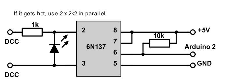
Beware that standard resistors have a 1/4W power rating … the 1k input resistor can get hot if your track voltage exceeds 15V. In that case use 2x2k2 in parallel.
We can’t use just any opto-coupler. The 6N137 is a fast one, which is needed because DCC decoding relies on measuring pulse width: 50µs is a ‘1’, 100µs is a ‘0’. A slow opto-coupler could distort this timing.
The output of the opto-coupler is connected to Arduino pin 2. This pin provides the hardware interrupt mechanism that is used with the Arduino DCC data decoding library. Do not change this pin or your DCC decoder won’t work.
Software
The software for a DCC accessory decoder is remarkably simple. Well … this is not entirely true, it is complex, but the complex part is taken care of in the DCC library … all we have to do is: #include <DCC_Decoder.h>
The DCC library can be downloaded here. Unzip it and move the folder to your Arduino libraries folder, usually found in My Documents/Arduino/libraries.
We need to configure our accessories. We fill in how many accessories are connected to this Arduino:
#define NUMACCESSORIES 2 // Enter the number of accessories here
Then in void setup() we fill in their Arduino pin numbers and the DCC addresses we want them to react to:
accessory[0].address   =  1; // DCC address
accessory[0].outputpin = 13; // Arduino pin

accessory[1].address   =  2; // DCC address
accessory[1].outputpin = 12; // Arduino pin
In this example only 2 accessories are configured. To add more, copy & paste, change the index pointer, pin number and DCC address.
The code for a complete DCC accessory decoder. The code contains a function (more about functions in a later later video) called: void BasicAccDecoderPacket_Handler(). This function switches our accessories on or off, based on DCC data read via the library. IMPORTANT: Roco decided to shift the addresses by 4. I don’t know why they did that, but if you use a Roco Maus or Z21, uncomment the line that says address = address – 4.
#define NUMACCESSORIES 2 // Enter the number of accessories here

// GO TO setup() TO CONFIGURE DCC ADDRESSES AND PIN NUMBERS

#include <DCC_Decoder.h>

typedef struct DCCAccessoryData {
  int   address;   // User Configurable DCC address
  byte  outputpin; // User Configurable Arduino pin
  byte  dccstate;  // Internal use DCC state of accessory, 1=on, 0=off
};
DCCAccessoryData accessory[NUMACCESSORIES];

// The DCC library calls this function to set / reset accessories
void BasicAccDecoderPacket_Handler(int address, boolean activate, byte data) {
  address -= 1;
  address *= 4;
  address += 1;
  address += (data & 0x06) >> 1;
  // address = address - 4; // uncomment this line for Roco Maus or z21
  boolean enable = (data & 0x01) ? 1 : 0;
  for (byte i=0; i<NUMACCESSORIES; i++) {
    if (address == accessory[i].address) {
      if (enable) accessory[i].dccstate = 1;
      else accessory[i].dccstate = 0;
    }
  }
}

void setup() {
// CONFIGURATION OF ACCESSORIES
// Copy & Paste as many times as you have accessories
// The amount must be same as NUMACCESSORIES
// Don't forget to increment the array index
  accessory[0].address   =  1; // DCC address
  accessory[0].outputpin = 13; // Arduino pin

  accessory[1].address   =  2; // DCC address
  accessory[1].outputpin = 12; // Arduino pin
// END OF CONFIGURATION OF ACCESSORIES

  DCC.SetBasicAccessoryDecoderPacketHandler(BasicAccDecoderPacket_Handler, true);
  DCC.SetupDecoder( 0x00, 0x00, 0 );

  for(byte i=0; i<NUMACCESSORIES; i++) {
    pinMode     (accessory[i].outputpin, OUTPUT);
    digitalWrite(accessory[i].outputpin, LOW);
  }
}

void loop() {
  static int n = 0;
  DCC.loop(); // Call the DCC library to read incoming DCC data
  if( ++n >= NUMACCESSORIES ) n = 0; // Next address to test
  if (accessory[n].dccstate)
    digitalWrite(accessory[n].outputpin, HIGH);
  else
    digitalWrite(accessory[n].outputpin, LOW);
  }
}
Just 60 lines of code … that’s it. The video shows it under test with my DR5000. I have 6 LEDs connected to pins 14-19 (A0-A5). The DCC output is connected to the opto-coupler input, a Switch window is opened and when I toggle DCC addresses 1 – 6 the LEDs switch on or off. Yes … that works perfect!
In the next video we are going to make a DCC servo decoder.
— 0 —

Hallo Rudy,
Als ik je voorbeeldbestand compileer, dan krijg ik de onderstaande melding. Ik heb dan nog niets aangepast en alleen van te voren de DCC bibliotheek geïnstalleerd. Wat gaat er fout?
——————-
C:\Users\Gebruiker1\Documents\Arduino\sketch_dec14c\sketch_dec14c.ino:7:1: warning: ‘typedef’ was ignored in this declaration
typedef struct DCCAccessoryData {
——————-
Groeten, Mark
LikeLike
Als je typedef in die regel weghaalt zodat ie begint met struct … dan denk ik dat die warming verdwijnt.
LikeLike
Hi Rudy,
This is a great code and circuit, thank you. When trying to use it to control 16 outputs through 2 sets of 8 x relays, the digital ports 3 to 12 work fine but with the analog pins A0 to A5 (13-18) the reaction is terribly slow, useless in practice. Any clue? Thank you. Joaquin.
LikeLike
Well, that is strange, I never noticed any delay on A0-A5. Could it have anything to do with A0-A5 having pin numbers 14-19, and not 13-18 like you mentioned?
LikeLike
Thank you for your reply. Yes, the analog pins are 14-19, sorry, was a mistake. I begin to think this is not a problem with the analog pins. It is some kind of saturation (optocoupler?). I have tried with a Mega 2560 (so with lots of digital pins) and everything goes well until I increase the number of pins connected to the relay array. The connectivity is fast until 8 relays are connected but when I index more accesories the control progressively slows down. Everything above 11 is impossible. I think I will use and independent card for every 8-array. the only way i find.
LikeLike
Well, this is very strange of course, since the Arduino is not aware what kind of unit is connected to its outputs. Have you checked the speed if you test the outputs with an LED plus resistor?
LikeLike
Rudy, I may confirm now that the problem is reproduced with led+resistor array. So this is not a poblem with the load or any other problem with the relay array. I have checked the relay array with a simple script and the arduino board is able to control the array with no problem. Any other idea? thank you!
LikeLike
OK, that is what I expected, the type of unit connected to output pins should not make any difference. So the issue is that with the DCC decoder software, when you try to control ports 14 – 19 they respond slow? Weird, because in the code it makes no difference if you control pin 5 or pin 15. What happens if you configure it to only control 6 outputs on pins 14 – 19. Then add outputs 3 -12. Are you sure your DCC signals are coming through with the speed you expect?
LikeLike
I agree, the type of output is irrelevant. It seems that there is no difference with the order or pin type. For example you can use 14-19 plus 3-4 efficiently -no problem at all- but then as soon as you incorporate 5-6 then you begin to get troubles. So it is not related to the nature of the pins but connected with the number of pins (>8 pins = trouble). In fact, as I told you you, I can use a Mega just with logical pins and the problem is exactly reproduced; cannot control more than 8 pins efficiently. What about the DCC signal converter through the optocoupler, may be a problem with the number of signals being controlled?
LikeLike
have you tried using a switch statement instead of a for loop ? A loop iterates through all the addresses, whereas a switch statement with a whole heap of cases can be a lot quicker. This is not something that is recommended by modern coding standards, but is very common in old embedded firmware implementations.
Also, although it doesn’t usually make a difference, I have noticed that the Arduino compiler doesn’t always handle compound statements correctly I would always use curly brackets to encapsulate the contents of a IF statement – even if it is just a single line.
LikeLike
Do you have a parts list and sources for the optocoupler circuit you built. Thks
LikeLike
Schematics on this page: https://rudysmodelrailway.wordpress.com/software/
LikeLike
Hi Rudy. My name is Hans. I’m running g scale in my garden and want to use your accessory decoder idea at remote places, powered by the DCC signal from the track. I was thinking of using the input ports of the Arduino Uno also for sending block occupancy (reed switches) status to the command station (Arduino Mega). Is this possible and does it need extra doing or is it handled by the dcc-decoder.h library. Thanks for answering.
LikeLike
Hans, DCC decoders and sensor feedback can not be combined in one Arduino. For the feedback you need an S88 bus and the Arduino S88 software available in my download, or you can use Arduino based Loconet module. I’d advise you to have a look at this website: http://www.arcomora.com and get yourself the DDCnext modules and the Arloco shields. They are cheap and all the software you need is free and extensive user manuals are available.
LikeLike
Hi, This looks fantastic. I want to get this running and control some scenery LED lights on my son’s railway. Can you point me to the bits I need to buy? I have a background in programming but no experience with arduinos.
LikeLike
All you need is an Arduino Uno and some parts for the opto isolator circuit that is shown on the /Software page. You can also build a DCCNext module using the info and the parts from http://www.arcomora.com.
LikeLike
Hi Rudy,
So I got the parts, built the circuit, no joy – I can’t get it to work.
We’re using a Hornby Select controller, Arduino Uno, and the parts from your circuit.
Should the LED flash? Ours isn’t doing anything. Occasionally the Hornby Select goes OL for overload. I’ve checked the circuit and can’t find a problem.
I used your code above and when I verify it says the typedef is ignored. Not sure why.
I set it up with one accessory, address 15, Arduino output 13.
I then pick address 15 on the Select. I tried forwards / backwards direction, function on / off, and turning the speed dial. No LED from the arduino.
What do you suggest?
Thanks
Ant
LikeLike
A bit more progress, but we’re still stuck.
First off, our LED was the wrong way around on pins 2 and 3 of the opto. It now illuminates but we still can’t get the uno to turn output LEDs on and off in response to DCC packets.
I wrote a script to test the circuit and check the uno is getting interrupts and YES it is getting them.
The time between interrupts (timed using the micros function) is 12 or 16 us, ocassionally 40us.
I did try getting the uno to count the interruprs and it came to about 27,300 per second. That suggests they’re every 36us on average. Every second my script records the gap between the two most recent interrupts so that could be correct, but it mostly says 12us or 16us rather than the 40us which surprises me.
I notice in the DCC_Decoder.cpp it defines the min and max micros for zeros and ones to be:
#define kONE_Min 52
#define kONE_Max 64
#define kZERO_Min 90
#define kZERO_Max 10000
So if we’re getting an interrupt every 12, 16 or 40us then it’s not a zero or a one in DCC binary. So the library isn’t getting any valid packets.
So I’m still confused. Unfortunately I don’t have a oscilloscope to check what’s actually happening.
Any suggestions?
Ant
LikeLike
Hi Ant, I’ve sent you an email.
LikeLike
For anyone else picking this up – we got it working. The Hornby Select controller seems to need to have a railway connected to it as well as the arduino. At first I just had the Select and the Arduino and no packets were received. Once I connected up the trains too the arduino decodes accessories on addresses 60-99.
LikeLike
Hi Rudy,
I have made the decoder as shown in the video but it is not working for me (I have tested the optocoupler and I tried 3 arduino boards too). Maybe the problem is that I am using a Roco Z21Start?
LikeLike
With Roco the DCC addresses are shifted by 4, which means when you want to activate address 1 in the Arduino you need to activate 5 on the Roco. Of course we can change the Arduino code to subtract 4 to get them in sync. An alternative is to use the free software from http://www.arcomora.com , you can configure it via PC and you can tell it to work with Roco.
LikeLike
Hi Rudi – I know this is an old thread but maybe useful for other Z21 users : I changed the code to + 4 rather than – 4 and it works fine. The Z21 app or using TC have the same address as that I put in the Arduino code.
LikeLike
I shifted the addresses in the code but it is not working. I tried the DCC decoder library example called DCC monitor but it is just showing 0 packages. It seem like it is not reading the dcc signal.
LikeLiked by 1 person
This indeed sounds as if the signal on Arduino pin 2 is not OK. Is the hardware 100% according to the schematics? Do you have any means to measure? Can you try another opto coupler?
LikeLike
So I tried 2 optocoupler none of them worked but the third finally worked! Thanks for your help!
LikeLike
For me this works fine and solves a problem or two I had.. so thank you 🙂 As a question… all the addresses seem hardcoded in the program.. is there a way to add a programming button with a LED so that when pressed, the first address received is the one that is accepted with the rest daisy chaining as needed to the maximum no of adresses and once programmed resets so the LED goes out?
Whilst hard coded works without a problem, it would be nice to get a little more flexibility for multiple boards etc without having to check the right board is setup for the right addresses. Currently I have three sketches for my three boards and I have to remember on changes which board is being changed 🙂
Regards
Graham
LikeLike
Have a look at http://www.arcomore.com and give the free MARDEC software a try. You can configure your Arduino DCC decoders via PC USB interface.
LikeLike
Can you confirm for me:
I am using Peco Solenoid three cable point motors. Obviously each motor has two solenoids, for each direction of the point.
Does this mean I would need to use two Arduino pins (and two relays) for each point?
LikeLike
Yes, that’s exactly how it should be done. And use the DCC decoder sketch suitable for solenoid drives. Easiest would be to use the free MARDEC software from http://www.arcomora.com
LikeLike
Thanks Rudy. I will check out the Mardec software.
LikeLike
Hallo Rudy
I tried Mardec. It did work well but a couple of things took me back to your code. Mardec is pre-compiled which means I cannot play with it! It also has a problem using pin 13 on a R3Uno (due to built in LED).
I added a modification to your code to switch dual-solenoid motors. The problem I have found is that the pin state is set HIGH correctly but then the program seems to ‘stick’, the LED stays on after the delay.
If I send the DCC off signal to that address the LED does not turn off either.
I apologise if this is due to my lack of programming skill but I am unable to get it to work.
Thank you in advance.
void loop() {
DCC.loop();
for (byte i = 0; i < iNoAssessories; i++) {
if (accessory[i].dccstate) {
digitalWrite(accessory[i].outputpin, HIGH);
delay(500);
digitalWrite(accessory[i].outputpin, LOW);
}
else {
digitalWrite(accessory[i].outputpin, LOW);
}
}
}
LikeLike
Can ‘t use a delay in the code, it will mess up DCC decoding. If I remember well these is a solenoid file available in the zip download on the software page. If it’s not there, let me know and I’ll send it to you.
LikeLike
Yes, I found the file you meant: DCC_Basic_Acc_Decoder.pde
Works well, thank you.
LikeLike
I don’t know where you found that … I never use.pde extension, only .ino. And the file should have solenoid in the name. I’ll send it to you this weekend.
LikeLike
Thank you
LikeLike
Hello Rudy,
Thank you so much for this guide, it works very well and very impressed.
I would like to know, instead of building the components, can a motor shield be used to sniff out the DCC signals?
I have a motor shields here but couldn’t work out how to use it in a similar way.
Thank you so much in advance
Andrew
LikeLike
To be honest I have no idea what you mean. What part(s) whould you like to replace by a motor shield?
LikeLike
Sorry, maybe i could of explained further. I would like to replace the DIY opto-coupler circuit you have put at the top of this post that reads the DCC signals from the track with a pre-made motor shield so that the signals can be read and the Arduino.
LikeLike
If your motor shield has the same optocoupler circuit on, then the answer is yes … but I doubt it has?
LikeLike
Hi RudyB,
Hope you doing well.
I need some guidance with this dcc-decoder application.
I have a Uno and made up the interface circuit as per the diagram.
I’m running a Digitrax DCS51 command station from where I would like to switch the accessories on and off.
I have uploaded the sketch, as per the document, to the Uno successfully.
When I apply power to track the LED on interface board lights up. All good.
By activating the accessory addressing, which I programmed in the code, nothing happens.
I have LED’s connected to the relevant outputs to check for on and off activity.
No activity on the LED’s.
Thank you.
Rudolf.
LikeLike
I’ll send you an email then you can send me your code and I’ll have a look.
LikeLike
Hello Rudy,
my two xomments concerning hard- and software:
– there’s no need to force so much current into the 6N137 optocoupler LED. According to the datasheet, 20 mA forward current is maximum rating and a 5 mA operating current is recommended, so the 1 kOhm resistor should be replaced by 3.3 kOhm. I tested this his working down to 12 volts DCC rail voltage. At 18 volts, the resistor now dissipates only about 80 mW instead of 270.
.- for operation with Roco, the address shifting line in the software has to be address = address + 4, otherwise the addresses are shifted in the wrong direction.
But anyway: Thanks for the nice software suggestion, easy to adapt and works fine on my arduino nano (compatible board with CH340 USB-serial chip).
Best Regards,
Dirk
LikeLike
Hi Rudy,
Geweldige voorbeelden wat je allemaal kunt met Arduino. Ik wil graag de
DCC Accessory Decoder gan proberen om lampjes te laten branden via DCC.
Mijn vraag is eigenlijk of dat er complete bordjes zoals jij die hebt in
je video met de opto-coupler 6N137 te koop zijn bijvoorbeeld bij Ali?
Zo ja zou je dan ook een artikel nummer of product aanduiding kunnen geven
Ik ben namelijk niet zo handig dat ik dat zelf zou kunnen maken.
Alvast bedankt voor je antwoord.
Wil
LikeLike
Die zijn wel ergens te koop in the UK, maar die zijn schreeuwend duur. Een heel goed alternatief is om EEn DDCNext bordje te kopen bij http://www.arcomora.com. Niet duur en alles in 1, Arduino, optocoupler, en servo en schroef connectoren.
LikeLike
Hi Rudy,
Bedankt voor je antwoord. Ik heb een DCC Power Shield van ArCoMoRa (Mardec).
Het schema van dit bordje is bijna hetzelfde als jou schema hierboven ook met
een 6N137. Kan ik dit bordje gebruiken als opto-coupler tussen de centrale en
Arduino. Zo ja hoe sluit ik dit dan aan. Het Mardec bordje heeft een 5V en
GND aansluiting. verder nog 16 aansluitingen genummerd 3 t/m 19. (13 ontbreekt)
2 DCC aansluitingen en nog 2 aansluitingen 7-12V dc/12-18V AC.
Ik hoor het graag.
LikeLike
Ja, die kan je prima gebruiken. Gewoon op de Arduino steken. Hoe e.e.a. aan te sluiten os beschreven in de handleiding die beschikbaar is op de arcomora website.
LikeLike
maar gebruik ik dan de Mardec software of jou schets zoals hierboven en in het filmpje.
LikeLike
Kan allebei. De Mardec software is gebouwd op dezelfde basis sketch, heeft als extra de configureerbaarheid via de PC zonder zelf in de code te hoeven duiken.
LikeLike
Hello Rudy.
Does Your code work on the Nano Every aswell ?
LikeLike
Yes it should work perfectly fine.
LikeLike
Hi Rudy,
First thank You for this great Job!
I put The Program (wrote) IDE Exactly as You show but still nothing happen…every things ok in the program, no mistake upload ok Arduino is pro one 25€. (Not China) and working fine with others programs.
I use Arduino Nano 33 BLE and output array circuit ULN 2803AN, this, to command 2 relays or coils etc..theses circuit can accept very low voltage In the Input. and 3.3V from The Nano33 BLE is ok.
My problem is the signal is coming-out from the Opto 6N137 I can Check it with an Oscilloscope the signal is changed when activate an accessories with My Z21 Roco. (I Know about address+4, Etc..)
But Nothing output on pin 3, or 4 (I modify INO Prg) of course…instead of pins 12, pins13…etc.
The input DCC Signal is sure Pin 2 (D2) Not RX…?? No confusion…?
Because How the Nano Know about pin 2 That is normaly Int 0 ? No?
I may mistake somewhere ?? Loool!!!
I Just want to used this for 2 turnout or ( Railway switch)
Can You help me
Any way thank You for Your Job is great
Very best regards
Jean Louis
LikeLike
Hallo Ruud,
Zijn de opto-coupler 6N137 als module zoals jij die gebruikt ook kant en klaar te koop. Zou je een link
kunnen geven welke je dan zou moeten hebben.
Alvast bedankt
Wil
LikeLike
Ik heb ooit een linkje (ik weet niet meer waar, misschien te vinden via Google) gezien van iemand in de UK die een module aanbood, maar voor wat ik vond een belachelijk bedrag. Wat je beter kunt doen is een DCCNext of een Arduino DCC Power Module kopen bij http://www.arcomora.com. DCC software is daar ook gratis te downloaden.
LikeLike
Hi Rudy,
Ben jij het volgende probleem al een keer tegen gekomen?
Ik heb een DCCnext shield van arcomora met software voor sein besturing. Het was makkelijk te bouwen en werkt heel mooi in combinatie met DCC++Ex.
Behalve als een van mijn locs, de Br151 (met een mSd/3 decoder en koolborstel ) motor op de baan actief is.
Dan worden veel Dcc opdrachten niet gezien. Met andere loc geen enkel probleem.
Helaas heb ik alleen een multimeter, dus kan het DCC signaal niet meten.
Heb jij een paar tips hoe ik verder kan zoeken dan wel oplossen wat de oorzaak is?
Met vriendelijke groet Rens
LikeLike
Hoi Rens. Dat is vervelend. Ik heb hier ook ervaring mee. Op sommige van de banen waar ik bij betrokken was voor de besturing reed een locomotief die de veroorzaker was van storingen. Soms hielp een andere loc decoder, soms hielp het plaatsen van (ontstoor) condensatoren op de Arduino 5V/GND, soms hielp niets … het enige wat je dan kon doen is die betreffende loc niet laten rijden.
LikeLike
Hi Rudy,
Just to inform you. I tried a number of resistor and capacitors combinations at input and output of the optocoupler to get rid of the disturbances in the DCC signal which are produced by the Marklin BR151 loc.
Although some improvements were noticeable it still not satisfying . So I decided to create a second DCC bus system ( Dcc++ Ex) dedicated for all the accessories DCC decoders. All problems are solved now, and it works perfect.
LikeLike
That’s good news. Good idea to create a separate DCC line.
LikeLike
Hoi Rudy, dankjewel voor de snelle reactie. Ik ga eerst de met de condensatoren aan de slag. Hopelijk helpt het. Verder zag ik ook het gebruik een kleine condensator op het DCC signaal net voor de 6N137, Ik meld me wel even voor het resultaat.
Met vriendelijke groet Rens
LikeLike
I warmly welcome
Could it be done so that each connected output was active for, say, 10 seconds (set)
Regards Irek
LikeLike
Yes, that can be done. There is a version of the code that allows for different modes, among then is a ‘one shot’. Download the api file from https://rudysmodelrailway.wordpress.com/software/
Alternatively you might want to have a look at the free MARDEC software form http://www.arcomora.com.
LikeLike
Thank you so much, that’s what I meant
LikeLike
Hi Rudy, I have with great interest seen your ‘Fun with arduino’. I tried your DDC servo solution with my Z21. I struggle a bit with this, have to push the Z21 icon several times before some happen. ( I’m aware of DDC address differerance). So I wonder are there changes in software in order to make it stable for z21 use. Thanks Arie-Jan
LikeLike
If your command only comes thru every now and then, my guess is there is disturbance on the DCC signal, or the Z21 DCC timing is oj the limit of what the Arduino expects.This timing can be changed in the DCC library, but chances that this is the cause and a change will solve your issues are slim.
LikeLike
Hello Rudy, and thanks for a splendid turorial.
I have a “small” issue, regarding the 5V supply to the optocoupler. If I connect the +5V directly between the UNO (pin 5V) and the optocoupler, aswell as the GND directly between the UNO (GND) and the optocoupler, everything works fine.
The moment I put something in between the UNO (pin 5V) and the optocoupler, like a breadboard (uno to breadboard and from breadboard to optocoupler, the signal from the optocoupler to the interrupt pin (pin 2), does not go through.
I might need this feature for using the 5V for other things also, like potentiometers and such.
Do You have any idea what might be the problem ?
I have seen additional optocoupler layouts, where the 10k resistor is between pin 7 and 8, and a 4,7k resistor between pin 6 and 8. Could this maybe help ?
Br. Anders
LikeLike
Hello Rudy, it might have been a faulty connection. It seems to work now even with the breadboard.
LikeLike
Hello, is it possible to use Your code (Fun with Arduino 29 DCC Accessory Decoder) together with a PCA9685 via i2C, to control multiple turnouts (servomotors) ?
I have tinkered a little with it, but can not get it to work.
LikeLike
Great!
LikeLike
Hello Rudy.
the issue with the faulty connection solved my question regarding the optocoupler.
My question regarding the I2C (PCA9685) still stands.
Br. Anders
LikeLike
Hi Rudy,
Thanks for the great explanation and video.
I’m new to Arduino and would like to use one, and your sketch, to drive Tortoise point motors on my layout.
I see the resistors on your LED array, so I presume the output of those pins is about less than the 5V input.
How do I get the 10-12V to drive the Tortoise motors?
Also, is a 6N138 Darlington optocoupler interchangeable with the 6N137 you specify?
(They are readily available at my local electronics shop. They don’t stock 6N137.)
Thanks
Erik
Sydney
LikeLike
The Arduino runs on 5V. To drive a 12V servo motor a FET must be used in between, unless the servo only uses 12V as power but has a 5V logical input. I don’t know the Turtoise … you’ll have to look over their documentation to find out how to do this.
About the opto coupler, it needs to be a high speed one. You can look up the 6N137 timing specifications … any alternative should not be slower than that.
LikeLike
Tortoise point machines are analog slow motion stall motors in wide use in USA & Australia. They are powered by 12V or less and draw about 15 mA at stall.
LikeLike
I had a look and from what I understand is that the motor is controlled by internal electronics and to switch the turnout electrical switches are used. For these you could use Arduino relays like these:
https://www.aliexpress.com/item/32649659086.html
They can be directly controlled by an Arduino output. Using these relays as intermediate you can use the Arduino DCC Accessory Decoder sketch to switch your Tortoises.
LikeLike
Hi Rudy,
The classic Tortoise machine contains a simple stall motor activated one way or the other by the 2 outside pins of the 8-pin connector. There’s no electronics. I drive mine with + & – 8VDC.
http://www.circuitron.com/index_files/Tortoise.htm
The 6 inner pins are 2 DPDT switches (driven off the motor gear) that can be used to switch signals, frogs, indicators, etc.
They are the point motor of choice by modellers who want prototypical point switching and tens of thousands are installed on US and Australian layouts.
And your suggestion about the Arduino relay is exactly what I need!
But I have a question:
Does Arduino remember its last state? ie, on power-up, what would be its output to the relays?
If I had a loco straddling a set of points, I wouldn’t want the points to change when I turned on the system,
Thanks
Erik
LikeLike
Hi Erik, yes the relays are what you need to separate the Arduino 5V from the Tortoise 8V.
For the software … a railway friend of mine adopted and enhanced the software such that it uses the internal EEPROM to store and retrieve the state of every output. Also the software is fully configurable via PC and USB. It is called MARDEC and can be downloaded for free at http://www.arcomora.com. A User Manual comes with it.
In stead of using standard Arduino’s you could also consider getting the DCCNext modules he offers on his site at a very interesting price point (material costs plus shipping, almost zero profit). It’s a DIY kit, it contains all the parts needed and only requires some soldering. A step by step soldering manual is available. It also has the convenience of screw terminals for the wiring of accessories, or 3 pin connectors for servo’s.
LikeLike
Thanks once again Rudy. That site, like yours, is full of good info.
It looks like I’ll be able to do exactly what I wanted. I’ll explore it in depth and decide which way to go, although, being a tinkerer and wanting to learn more about Arduino, I’ll probably want to build it myself.
I’ll keep you informed.
Thanks for all your help.
Erik
LikeLike
Have fun, which ever path you choose.
LikeLike
Dear Rudy
I will be using multiple Arduino Duo boards as have many points to control.
Can I use one optoisolator to connect to all the Arduino boards. Or, will I need one optoisolator board for each Arduino?
Thank you in advance.
LikeLike
It’s possible to use one opto-coupler circuit as long as the distance to the Arduino’s is short. Hard to tell at what distance trouble may start to arise … I’ve worked with 3 feet, but the shorter the better.
LikeLike
Thank you for the quick reply. I will bear in mind the distance.
LikeLike